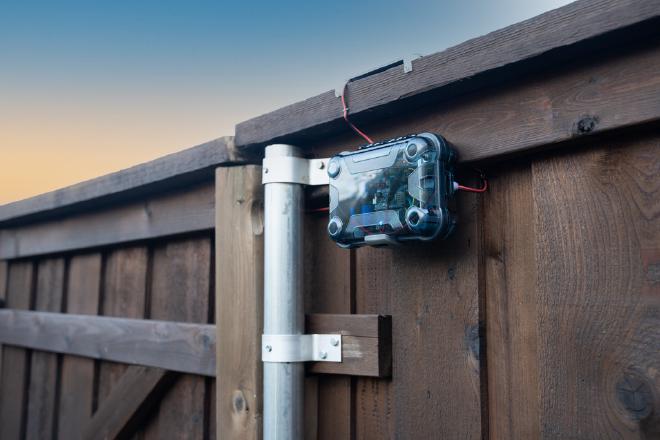
HomeKit Connected Fence Door Monitoring System

Table of Contents
Summary #
The objective of this project is to create a solar powered, HomeKit connected outdoor fence door monitoring device. Once setup, the door’s state (i.e. open/close) can be monitored and used in automations within the HomeKit ecosystem. I’ve been using it for months now, and it has been working really well. See below a video of the system in action.
This is not a difficult project, but there are several moving parts associated to it, so I’ll try to be thorough in the following sections.
Hardware #
The diagram below shows all the hardware components and how the communicate with the Homebridge server and mobile devices.

Note that there is an Additional Door Switch in the diagram. We will be using just one switch, but everything will be wired and ready to connect a second switch if needed (e.g. two-door fence or a more complicated setup).
Here is the list of hardware components used in the project:
- Adafruit M4 Express.
- Adafruit Airlift ESP32 WiFi Co-Processor.
- Adafruit Universal USB / DC / Solar Lithium Ion/Polymer charger.
- Adafruit FeatherWing Doubler.
- Medium 6V 2W Solar panel - 2.0 Watt.
- Mini solderable breadboard.
- Toggle switch.
- Terminal block connector.
- AWG 22 Silicone wire for internal connections.
- AWG 18 wire for connecting solar panel to terminal block.
- Door sensor magnetic switch.
- Screws: M2-0.4 6mm length, Zinc Plated Finish, Flat Head. These are used to attach the PCBs to the 3D printed frames.
- Screws: M2.5-0.45 8mm length, Zinc Plated Finish, Flat Head. There are used to attach the “corner adapters” to the outdoor case (more on this in the following sections).
- Brass inserts.
- Velcro strips for attaching battery to 3D printed support frame.
- Outdoor case.
Wiring and Soldering #
We’ll be using two of the controller’s digital inputs to monitor the doors state, pins D6 and D9 (here is the controller’s pinout diagram for reference). Since there is more than enough space in the case, I decided to do most of the wiring and soldering on a breadboard instead of doing it directly on the boards. The extra space allowed me to use a terminal block to facilitate connection/disconnection of the switch(es).
The following image shows how the terminal block is soldered to the small breadboard.

Three wires should be connected from the Doubler to the breadboard: Two coming from the digital input pins described above and one coming from GND. Additionally, in order to add an on/off switch, a fourth wire should be connected to the Enable pin on the Doubler. This wire should go to the toggle switch and from there to GND on the breadboard (here is adafruit’s explanation on how to add a switch to a feather board).
The image below shows the breadboard’s bottom side and the wire connections from the breadboard to the Doubler.

Finally, solder the included capacitor to Adafruit’s Solar Charger board. Here is Adafruit’s product description for more information.

Outdoor Case and 3D Printed Parts #
All STL files for the 3D printed parts can be downloaded from here. If you are planning to do all the 3D printing yourself, I’d recommend using PETG filament instead of PLA as it withstands higher temperatures better.
Since this device will be sitting outdoors, the case holding it should be water-tight and capable of withstanding the elements. There are many cheap cases available both online and at retail stores that perform just the same or better than a custom designed 3D-printed case. I decided to use the same one I used on a similar outdoor project some time ago.
The challenge of using an off-the-shelf case is fitting all components inside. To facilitate this, I designed 3D printed corner supports with brass inserts/threads.

These supports are attached to the case through screws that engage thin plastic tabs on the corners of the case as seen on the image above. Components and boards are placed on top of 3D-printed supporting frames that are later attached to these corner supports. Here is how the battery attaches to its frame using Velcro ties:

Before putting everything together, two small holes should be drilled into the case, one for the wires coming from the door magnetic switch (side of the case) and another one for the wires coming from the solar panel (top of the case). Then, the board supporting frames are screwed into the corner supports and cables are arranged to fit neatly around the boards.

Note that in the picture above, the solar panel was installed on top of the case and its cable (red cable) was routed through the lid into the case. Although this arrangement works fine, I did not go with it in the final design because the solar panel was not getting enough light during the day. This may have been because of my fence’s particular arrangement, so it might work for other people. In the final design, I mounted the solar panel facing up, on top of the fence as seen on the image below.
Remember to seal the case holes with silicone so that water doesn’t get inside.

Let me take a moment to explain the wiring situation on the image above. The solar panel’s wires (black and red wires which can be seen through the case’s lid) are routed into a hole drilled on top of the case. These wires connect to a long cable with a plug at the end which is inserted into the solar charging board. Black and red wires are connected to the terminal block on the breadboard, they go out through a hole on the case’s right hand side and are routed behind and to the left of the case. These wires connect to the magnetic switch installed on the fence door (not seen in the picture).
Software #
As seen in the diagram at the beginning, an always-on computer hosting Homebridge manages communication with HomeKit framework/devices. Additionally, the voltage supplied to the battery and the door switch status are monitored online through Adafruit IO portal. This allows us to keep tabs on battery performance and check if the solar charger is getting enough sunlight during the day to charge the battery.
Homebridge #
HomeBridge is an amazing piece of software that allows IOT devices to connect to Apple’s HomeKit framework. Installation is pretty straight forward, just follow the instructions here. As indicated above, it should be installed on an always-on computer.
One of HomeBridge’s key features is the amount of plug-ins made available by the community, from garage openers to Smart TVs and AC units. For this project, you’ll need to install the Webhooks plug-in, which is a general purpose web API. Follow the installation instructions on the plug-in’s website. Once installed, the following should be added to Homebridge’s configuration file:
{
            "platform": "HttpWebHooks",
            "webhook_port": "PORT",
            "cache_directory": "PATH_TO_HOMEBRIDGE_FOLDER/.node-persist/storage",
            "sensors": [
                {
                "id": "fencedoor",
                "name": "Fence Door Switch",
                "type": "contact",
                "autoRelease": false
                }
            ]
        },
Where:
PORT: default installation port (52828).
PATH_TO_HOMEBRIDGE_FOLDER: is usually Users/username/.homebridge on a Mac.
Once HomeBridge is installed and configured, it will run every time the computer is started up, with no additional interaction on your part.
Adafruit IO #
Adafruit IO is a platform designed by Adafruit to display, respond, and interact with IOT projects. It’s very easy to get started with, has a great user interface, powerful visualization tools and rock solid connection. They offer a very permissive free tier too (just be mindful of their servers and don’t hit them with many requests). I haven’t found a better or easier way to interact with IOT projects.
Here is a screenshot of a dashboard I put together showing supply voltage to the battery and switch status:

Microcontroller #
Code is written in CircuitPython. Follow Adafruit’s instructions for installing it on the M4 Express board.
All the needed files are included in the project’s GitHub repository. However, make sure to use the latest version of the needed libraries as Adafruit updates them fairly often.
Here is the list of libraries that need to be copied to the lib folder on the board:
- adafruit_esp21spi
- adafruit_bus_device
- neopixel.mpy
- adafruit_requests.mpy
- Adafruit_rgbled.mpy
- simpleio.mpy
The board’s root folder should have the following files in addition to the lib folder referenced above:
- secrets.py
- code.py
secrets.py
This file holds the credentials for the WiFi network and Adafruit IO. Here is what it looks like:
# This file is where you keep secret settings, passwords, and tokens.

secrets = {
    'ssid' : 'YOUR WIFI SSID',
    'password' : 'WIFI PASSWORD',
    'timezone' : "America/Chicago", # http://worldtimeapi.org/timezones
    'aio_username' : 'YOUR USERNAME',
    'aio_key' : 'YOUR AIO KEY',
    'server_ip': 'SERVER IP:PORT',
    }
The server_ip field refers to the computer’s IP and port on which Homebridge is running. All other fields are self-explanatory.
code.py
This file holds the main script, which handles the sensing logic, wifi connection and communication with Homebridge and Adafruit IO. I’ve included comments in the script to make it easier to read and maintain.
The script is constantly checking the status of the controller’s digital input (i.e. magnetic switch status). As soon as there is a change in status, it posts it to both Homebridge and Adafruit IO. Since WiFi communication is so power intensive and given the fact the ESP32 co-processor doesn’t have an “idle” or “sleep mode” implemented in CircuitPython, I had to get creative and find ways of saving power. After several hardware iterations and code tests, and thanks to the help of the people over at Adafruit’s Discord channel, I decided that the best way to preserve power is by disconnecting the WiFi co-processor right after each post to Homebridge and/or Adafruit IO. This is done by the lines with esp.disconnect() in the script.
Power preservation is also the reason why voltage and switch status data is sent to Adafruit IO every hour, instead of on a more frequent timeframe. This is defined in the POST_TIME constant at the beginning of the script.
If you are planning to leave the device outside or easily accessible by others and you feel a bit unnerved by leaving your WiFi network’s password out in the open, a good option might be compiling secrets.py using the mpy-cross tool and including the resulting .mpy file in the board instead. Although this is not the same as encrypting the file, it’s the next best thing.
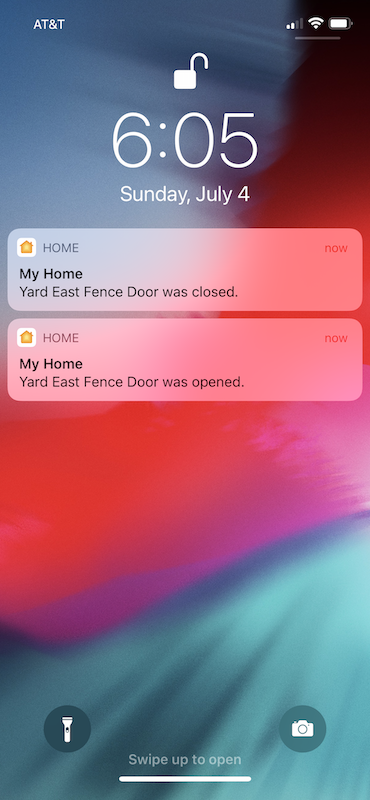
Here is a picture of a HomeKit notification being sent to an iPhone:

I had a lot of fun building and playing with this project. As always, feel free to either reach out to me or leave a comment below if you have any questions.
July 2021 Update
- Homebridge configuration code revised to show contact sensor type.
- Added screenshot of notifications on phone.
- Added link to YouTube video.