- Welcome to Moving Electrons!/
- Posts/
- Building a HomeKit Compatible Laser Trip Wire With CircuitPython/
Building a HomeKit Compatible Laser Trip Wire With CircuitPython

This post describes how to build a HomeKit compatible electronic trip wire to detect motion. As opposed to the more common infrared motion detection, there aren’t many options for detecting movement by interrupting a line of sight between two points. There are some alternatives that use infrared diodes, but those are limited by a maximum distance of just a few inches/feet between the emitter and the receptor.
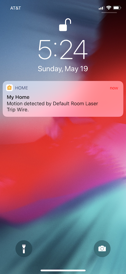
This project attempts to solve that limitation by using a regular laser emitter and a photo transistor as a receptor, so that the maximum distance is only dependent on the laser’s output power and your ability of aiming it to the photo transistor from afar. Once motion is detected, a notification is sent to Apple’s HomeKit framework via Homebridge, through a WiFi connection. That way, iOS devices can be setup to receive a notification through the Home App. The process sounds more complicated than it really is. Here is a schematic showing how all components interact with each other.
In the image above, the iOS device is shown outside the local network just to illustrate that capability. Most of the time I use the device from within my local network.
Some additional notes on the project:
- The emitting device uses a regular laser diode like the one used in commercial laser pointers.
- Both the emitter and the receptor use alkaline or rechargeable AA and AAA batteries.
- Configurable laser beam interrupting period before sending out alert to HomeKit (helps prevent false trips).
- “Almost” weatherproof enclosures (see notes below).
Hardware #
Laser Emitter #
This is probably the project’s less complex device. A regular laser pointer would do the job, but it would run out of battery quickly since it would always be on. The device I put together uses a general purpose laser diode connected to a weatherproof AA battery holder. A 3D printed small plastic support facilitates attaching the diode to the battery holder and keeping everything in place. Here is a list of the materials used:

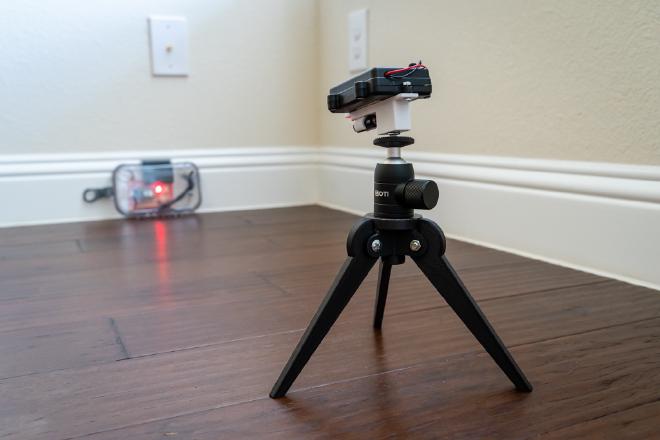
Attached to the 3D printed support is a 1/4-in metal adapter that can be easily mounted on a table top tripod or on a small ball head. This greatly facilitates aiming the laser beam at the receptor’s photo transistor.
Assembly is really straight forward, just insert the laser emitter into the plastic support and screw it into the AA battery holder. Then, either attach the assembly to a tripod or mount it as needed using the 1/4 inch tripod mount. The support’s files can be found in the project’s GitHub repository.

Laser Receptor #
This is the brains of the project as it handles all critical tasks: laser beam detection, WiFi connection and alert logic. The micro-controller used is the excellent Particle’s Argon board. Since I wanted the device to be used outdoors, I focused on weather proofing instead of portability. That being said, the device is fairly small and lightweight, so it can easily be moved/relocated.
The receptor case would be completely water proof if it wasn’t for the two mechanical switches on the front. Covering them before placing the device outside should make the whole assembly capable of withstanding inclement weather (just make sure it’s not submerged).
Here are the receptor’s main components:
- Particle Argon board.
- Toggle switch.
- Push button (normally open).
- Photo transistor. -LED diode.
- 220 Ohm resistor.
- 1 Kohm resistor.
- Weather proofed AAA battery compartment.
- Adafruit Feather headers(Optional). The Particle Argon board can be soldered directly to the breadboard. However, using these headers allows easy swapping of micro-controller boards.
- Breadboard PCB.
- Silicone wire AWG24.
- Weather resistant case.
Here is a general circuit diagram showing how components should be connected. Only the six Argon pins used (three on each side of the board) are shown for simplicity.

Since I used a prototype breadboard to build the receptor circuit and test the code, moving everything into the permanent PCB breadboard was a trivial task (i.e. no customized board was used). Here is an image of the final prototype:

Make sure the included antenna is attached to the Argon board as it is needed to establish a WiFi connection. Once the resistors, LED diode and photo transistor are soldered to the board, long wires for the toggle switch and the push button should also be soldered. The longer the wires, the easier to re-position the board inside the weather-proof case. Then, drill two holes on the front of the case for the switches and screw them in. Insert batteries in the battery holder and put everything inside the case.

As indicated above, once the case is closed, it’s almost weather-proof. Water would still get in through the switches’ holes, so make sure they are covered if you are planning to leave the case outside.
Software #
HomeBridge #
HomeBridge is an amazing piece of software that allows unsupported IOT devices to connect to Apple’s HomeKit framework. Installation is pretty straight forward, just follow the instructions here. It should be installed on an always-on computer. I’m using an old Mac Mini running MacOS X, but it can also be installed on other operating systems.
One of HomeBridge’s key features is the amount of plug-ins made available by the community, from garage openers to Smart TVs and AC units. For this project, you’ll need to install the Webhooks plug-in , which is a general purpose web API plugin. Just follow the instructions on the plug-in’s website. Once installed, the following should be added to Homebridge’s configuration file:
{
            "platform": "HttpWebHooks",
            "webhook_port": "PORT",
            "cache_directory": "PATH_TO_HOMEBRIDGE_FOLDER/.node-persist/storage",
            "sensors": [
                {
                "id": "laser1",
                "name": "Laser Trip Wire",
                "type": "motion",
                "autoRelease": false
                }
            ]
        },
Where:
PORT: can be the default installation port (52828).
PATH_TO_HOMEBRIDGE_FOLDER: is usually Users/username/.homebridge on a Mac.
Once HomeBridge is installed and configured, it will run every time the computer is started up, with no additional interaction on your part.
Micro-Controller #
All code is done in CircuitPython, which makes it fairly easy to read and maintain. Be advised that Particle doesn’t officially support CircuitPython. However, since their latest boards are very similar to some of Adafruit’s offerings (they have even adopted Adafruit’s Feather format), CircuitPython can be installed, but the process is a bit convoluted. Thankfully, people at Adafruit have done an excellent job describing the process in detail here.
Make sure you have the latest version of CircuitPython 4.x (I’m using their latest beta version) in addition to the latest version of their library bundle. Once the O.S. and libraries are installed, we are ready to work on the main script.
All needed files are in the project repository on GitHub, which includes the CircuitPython files and the STL file for the 3D printed case. The CircuitPython side is comprised of only two files: code.py and secrets.py, which are the main script and the file holding your network’s WiFi settings, respectively. The latter should look like this:
wifi_settings = {
    "ssid" : "YOUR WIFI_NETWORK_SSID",
    "password" : "YOUR_WIFI_PASSWORD"
}

server_ip = 'SERVER_IP:PORT'
If you are planning to leave the device outside or easily accessible by others and you feel a bit unnerved about leaving your WiFi network’s password out in the open (.. and you should), you can compile secrets.py using the mpy-cross tool and include the resulting .mpy file in the board instead of secrets.py. Although this is not the same as encrypting the file, it’s the next best thing.
The file code.py holds the main script, which handles the wifi connection, activation/reset and notification logic. Constants and configuration settings (e.g. waiting time before sending HomeKit notification) are located at the top of the file. I’ve included comments in the script to make it easy to change settings and modify its behavior.
Operation #
Usage is pretty straight forward, once everything is set up just follow these instructions:
- Placed the receiver securely in the desired place, making sure it won’t move.
- Place the transmitter in front of the receiver. Distance is not at concern as long as you are able to hit the photo transistor on the receiver with the laser beam. I recommend mounting the transmitter on a tripod ball head to facilitate adjustment.
- Turn the receiver on. A small blue LED should turn on to let you know the device is attempting to connect to your WiFi network. Once it succeeds, the LED will turn off.
- Turn on the transmitter and aim the laser beam to the photo transistor on the receiver (this is where the tripod ball head will come in handy). Once it hits it, the white LED will turn on to let you know you hit the right spot. This LED is big and bright, so you won’t have a problem seeing it outdoors.
- While the white LED is on, press the push button on the receiver for one second to turn it off. At this point the whole system is armed and as soon as the laser beam between the two devices is blocked (or they were to become unaligned), the receiver will send a notification through the HomeKit framework.

In order to disarm the system you can either press the push button again for one second or just turn off the receiver flipping the toggle switch.
Here is a video showing the setup in action:
I’ve had a lot of fun building and using this device. As always, feel free to either reach out to me or leave a comment below if you have any questions.
