
Security cameras seem to be have gotten pretty popular in the last couple of months. I thought I’d share how I put together one using a Raspberry Pi Zero W and some additional components.
The device has the following features:
- Powered by rechargeable battery. Battery charges via USB.
- Motion activated video (and photo) recording.
- IR LED equipped (night vision recording).
- Media saved locally (Raspberry Pi SD card), no need for Cloud storage or internet connection.
- If device is within reach of a WiFi network, it can connect to it and can be controlled through its web interface.
- Sends a notification to your phone and then shuts itself down when the battery is below a safe level.
- 3D printed case with standard tripod connector.
Hardware Setup
Here are the components used on this project:
- Raspberry Pi Zero W.
- Raspberry Pi Camera.
- Adafruit Power Boost 1000C.
- 4400 mAh Li-Ion battery.
- Latching push button switch.
- 3/8 inch tripod adapter.
- ABS filament for 3d printed case.
- Acrylic sheet.
- 22-gauge wires for connections between components.
The reason I went with the camera listed above instead of the official one is because the Raspberry foundation doesn’t offer a dual camera (i.e. night vision and daylight), you have to choose which one of those modes you will be using and get the corresponding camera. Since I wanted to use the device in both modes, I got an aftermarket product.
There are many models of these cameras offered online. Be careful with the one you get as not all of them can switch modes automatically (I’ve linked the exact model I bought above). Once you get the camera, you’ll have to calibrate it as settings are all over the place from factory. They don’t come with instructions on how to do that, so before I go through the calibration steps, let’s go over how the day/night mode shift works.
The way these cameras switch modes automatically is by utilizing a photo cell to switch an internal infrared (IR) filter on and off when the light level gets either high or low enough. We want the big Infrared (IR) LEDs turned on during night mode only, so that they don’t drain the battery. The high/low light threshold is set by two variable resistors which are very small screw-looking pieces located next to the photo cells. Thus, the calibration process is as follows:
- Dim down the lights in your room to the point where the night mode should kick in (or just turn off the lights if you want the night mode to kick in in almost complete darkness).
- Rotate one of the variable resistors back and forward using a small eyeglass screwdriver until the IR LED turns on (if it’s dark enough, you’ll notice a very dim red light coming out of the IR LED).
- Repeat the previous step for the other IR LED’s variable resistor.
It may take a while to set it up as the device is super sensitive, but once done, you’d be done with hardest part of this project.
Next the Power Boost device needs to be set up. Adafruit has a great tutorial going over every single detail of the device here. We’ll be using the following pins to interact with the Raspberry Pi:
- 5 Vo and GND. We won’t be using the micro-USB port on the Power Boost to feed the Raspberry Pi. Instead, we’ll be using these pins and will connect them to the appropriate pins on the Raspberry Pi’s GPIO header (see below).
- LBO. This is the low battery level pin.
- EN and 2nd GND. These are the “ enabling” pin and the ground pin respectively. Putting these together will turn the Power Boost off, and since it feeds the Raspberry Pi, it would effectively turn it off.
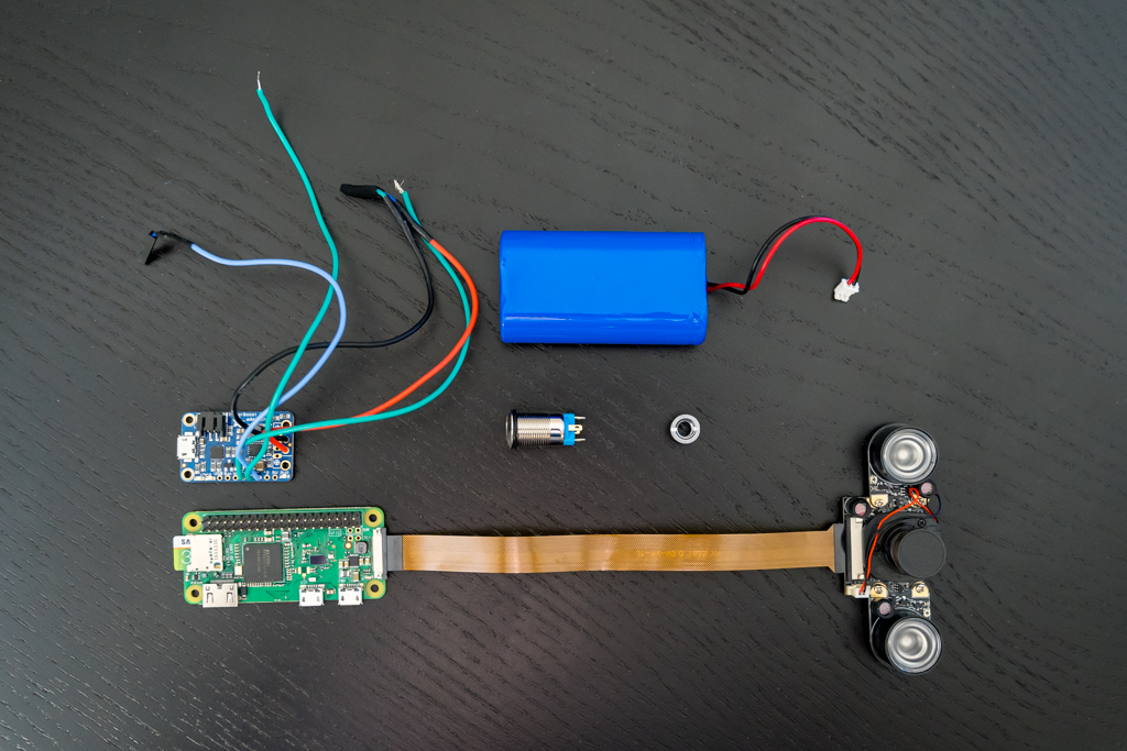
On the Raspberry Pi we’ll be using the following pins:
- Pin 2. This is the Raspberry Pi’s 5V rail, and we’ll be using it to power the device instead of the micro-USB port.
- Pin 6. Ground.
- Pin 36. This is the pin which the LBO pin on the PowerBoost should be connected to. It will be used to send a signal to the Pi to shutdown when the Power Boost detects low battery level.
More information on how to power the Raspberry Pi here. Note the following comment from that article, so proceed at your own risk:
Please be aware that there is no regulation or fuse protection on the GPIO to protect from over-voltage or current spikes.
Connect the corresponding wires coming from the Power Boost (items 1 and 2 in the listed Power Boost pins above) to the three pins on the Raspberry Pi’s GPIO header. You don’t need to solder the wires, you can just use jumper connectors for the connections.
Finally. Just connect the EN and second GND pin on the Power Boost (third item on the Power Boost pin description above) to the switch.
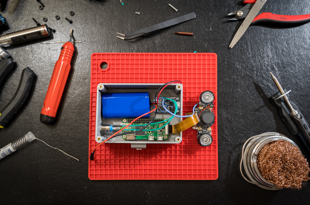
The picture above shows what all components look like inside the 3D printed box. Just don’t put them in the box yet, configure the software side of the project first.
Software Setup
This whole project hinges upon a wonderful piece of software called MotionEye OS.. from their main project page:
motionEyeOS is a Linux distribution that turns a single-board computer into a video surveillance system. The OS is based on BuildRoot and uses motion as a backend and MotionEye for the frontend.
Installation
- Format a mini SD card as FAT32. On a Mac, DiskUtility works just fine.
- Install MotionEYE OS on an SD card. The installations instructions describe how to do the process manually, but Etcher works faster and greatly simplifies the process.
Since the Raspberry Pi Zero W doesn’t have an ethernet port, your local WiFi SSID and Password information should be placed in /boot/wpa_supplicant.conf so that the device connects to your WiFi network. This file will be read every time the device boots up.
        country=US
        update_config=1
        ctrl_interface=/var/run/wpa_supplicant

        network={
            scan_ssid=1
            ssid=“MyWiFiSSID”
            psk=“S3cr3tp@$$w0rc|”
        }
More information here. Once installation is done, you can configure MotionEye OS to suit your needs per the instructions here.
Battery Power and Shutdown Scripts
Once the battery falls below a certain threshold (3.2v), the PowerBoost will cut power to the Raspberry Pi and will shutdown. Although the MotionEye OS partition is mount as read only to prevent file system corruption, it’s not the best way to turn off the Raspberry Pi.
The PowerBoost has an LBO pin that is normally set high (3.3v) and switches to low (0v) when the battery is almost depleted. I’m using this signal to shutdown the Raspberry Pi in such an event by connecting a wire between that pin and the GPIO 36 (board numbering) on the Raspberry Pi. Additionally, a notification is sent to my phone through pushover before the RPi is shut down.
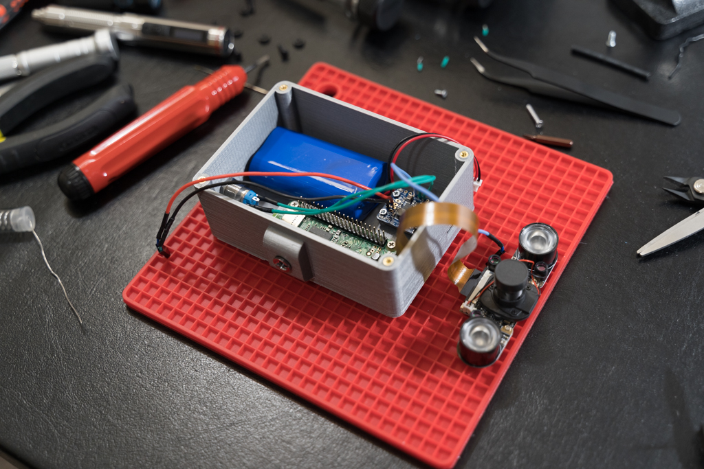
I based the Python scripts below on this excellent group and MotionEye OS documentation. In a nutshell, what we are doing here is loading the main script (safe_shutdown.py) in memory every time the Raspberry Pi is turned on, so that it is “listening” to the signal on Pin 36 of the Raspberry Pi’s GPIO. Once the the Power Boost sends the Low Battery signal, the script sends a message through pushover to a phone (or any other mobile device) and safely shuts down the Raspberry Pi.
Assuming the Raspberry Pi is connected to your WiFi network, connect to it through ssh and type the following to mount the drive as Read/Write: mount -o remount,rw / (use the same Username and Password setup when configuring the device).
Then, create two scripts with nano /usr/sbin/message.py
#!/usr/bin/python

import sys
import httplib, urllib

def pushover(message):
    conn = httplib.HTTPSConnection(“api.pushover.net:443”)
    conn.request(“POST”, “/1/messages.json”,
      urllib.urlencode({
        “token”: “YOUR PUSHOVER TOKEN HERE”,
        “user”: “YOUR PUSHOVER USERNAME HERE”,
        “message”: message,
        “sound”: “falling”,
      }), { “Content-type”: “application/x-www-form-urlencoded” })
    conn.getresponse()
    return

if __name__ == ‘__main__’:

    pushover(sys.argv[1])
And nano /usr/sbin/safe_shutdown.py:
#!/usr/bin/python

import os, sys, time
import RPi.GPIO as GPIO
from message import pushover

GPIO.setmode(GPIO.BOARD)
GPIO.setup(36, GPIO.IN) # 3rd pin up from the second row.

while True:
	if GPIO.input(36) == GPIO.LOW:
		print(‘Pin set to low. Sending message…’)
		pushover(‘Low battery on Picam detected.\n Shutting camera down.’)
		print(‘Turning Raspberry Pi off…’)
		os.system(“poweroff”)
		sys.exit()
	time.sleep(5)
Note: message.py can be called from the WebUI (commands section) to send messages through pushover upon certain events like so: python /usr/sbin/message.py “message”
Make the files executable by doing:
chmod+x /usr/sbin/message.py
chmod+x /usr/sbin/safe_shutdown.py
MotionEyeOS runs the script on /data/etc/userinit.sh at every boot. So, we just need to create that file and add the following line to it:
(/bin/sleep 240 && python /usr/sbin/safe_shutdown.py)&
That last command sets the Raspberry Pi to wait 4 minutes (240 seg.) on each boot before running the safe_shutdown.py script in the background (in case there are issues with it, you can log in before the script is called).
That’s all that needs to be done on the software side. The security camera is almost done, now we just need to give it a proper housing.
Case
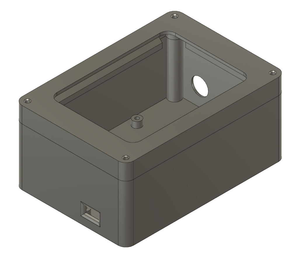
At this point, the camera is fully functional. Components can be arranged inside a generic project box (check box dimensions first to make sure everything fits inside) or build your own. I designed and 3D-printed a case comprised of the following two parts (here are the STL files, feel free to use them to print your own):
- Lid: Designed so that a a transparent acrylic sheet can be adhered on the backside.
- Case: The actual case has openings for the on/off switch and the micro USB port for charging the battery. Also, a 3/8-inch threaded adapter can be inserted in one of the sides, so the camera can easily be mounted on a tripod or a variable friction arm.
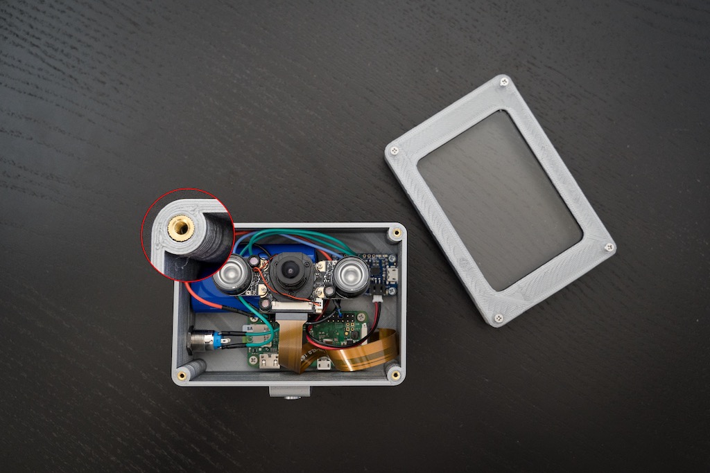
The image above shows the brass inserts on the corners of the case. They are embedded in the case using a soldering iron and allow for the lid to be screwed securely on top without leaving any gaps.
Since I wanted to use the camera outdoors, I printed the case in ABS, so it can better withstand his temperatures. However, keep in mind the case was not designed to be watertight.