Building a DSLR Camera Wireless Controller
I’ve been experimenting with time-lapse shots for a while now. Unfortunately, time-lapse shooting options on most DSLR and mirrorless cameras are somewhat limited. At the time of this writing, Sony doesn’t even include the feature on their high end cameras by default (you need to buy an “App” and download it to the camera).
Some time ago, I posted the setup I had been using for shooting time-lapses using a Raspberry Pi, a portable battery and a USB cable. It got the job done, but using a Raspberry Pi as a time-lapse controller seems a bit overkill. I also wanted to get rid of the cables and the need for carrying around a big battery pack. Thus, I came up with this little device.
Project Overview #
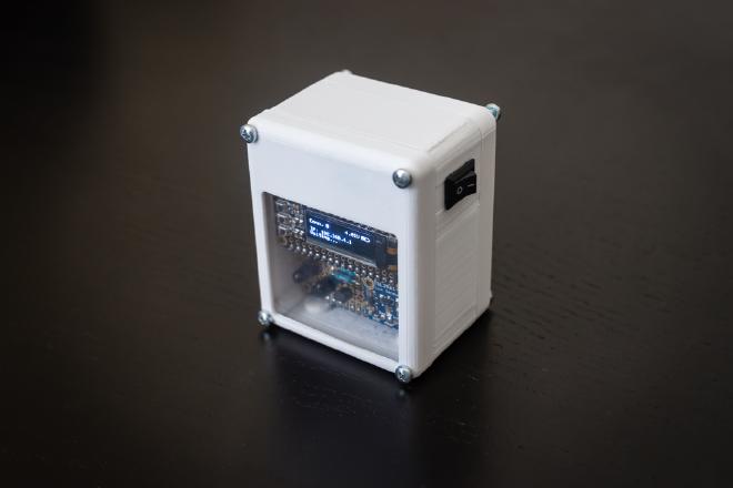
The main objective of this project is to put together a device for controlling photo shooting sessions (i.e. time-lapse, timer, etc.) taken with a Sony A7II mirrorless camera. The device’s main features are:
- Portable device with embedded/internal battery.
- Wireless interaction with camera through infrared (IR). No USB cables or special adapters to deal with.
- Multiple time-lapse options controllable through a web interface.
- Timer capabilities.
- On-device screen showing current status.
- Capability of doing lightning detection/photography. Although fully functional, it’s currently an experimental feature.
- Magnetic attachment to metal surfaces.
- Tripod mount.
Here is a video showing the initial connection and Timer feature:
This will be a long and detailed post. If you are a nerd (like me), I guarantee you the lines below will get your geeky juices flowing. So grab a cup of coffee, sit tight and enjoy.
Hardware #
Below is the complete list of the hardware used on this project. Most of the components can be found on Amazon.
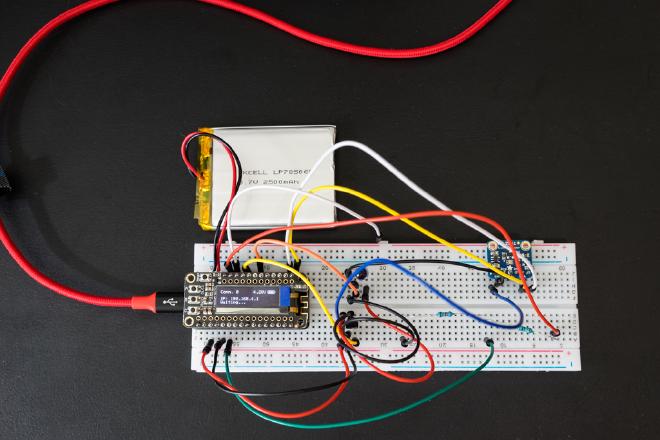
- Adafruit Feather Huzzah.
- Adafruit FeatherWing OLED.
- Adafruit Stacking headers (for Feather Huzzah).
- Adafruit FeatherWing Proto.
- Adafruit IR sensor.
- Adafruit Doubler.
- Super bright 5mm IR LED.
- Adafruit Li-Ion Battery 2500 mAh.
- 1 NPN transistor.
- 2 Resistors: 220K Ohms and 1 MOhm.
- Adafruit Digital Light / Luminosity / Lux sensor.
- Toggle switch (these are really nice).
- Magnets.
- Flexible silicone wire - 24 AWG (it doesn’t have to be silicone coated, I just use that type because is so easy to tuck between/beneath PCBs.).
As you can tell, I’m a big fan of Adafruit. They offer high quality products, well designed and made in the U.S. Their support is excellent and they offer a plethora of video tutorials and educational resources through their learn system available for free to the masses. This website is not sponsored by them in any way, I’m just happy to support such a great company.
Software #
General Setup
All needed files are in the project’s repository on GitHub. Before downloading the sketch to the Feather Huzzah, make sure components are properly arranged on the breadboard. Here is a diagram showing connection details.
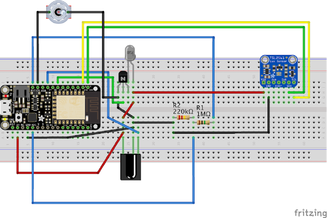
As seen above, there is really just a few components. From left to right: the Feather Huzzah (ESP8266 WiFi microcontroller) on top of which the FeatherWing OLED display (not pictured) will be attached. Down to the right, an Infrared (IR) light sensor (originally tuned to 38Khz so it’s capable of receiving commands from regular remote controls). This sensor is used only to learn new remote control IR codes. Going up from the IR sensor, there is a regular NPN transistor and an IR LED which is used to send the IR commands to the camera. The transistor is simply used as an amplifier to the IR LED signal. Moving to the right, there are two resistors that form a voltage divider which needed to read the battery voltage through the Huzzah analog input. Finally, we have the Lux Sensor breakout which is used for lightning detection.
Arduino Sketch
This was my first project working with Arduino code, which is basically C code. It has been a while since the last time I worked with the language, so it took me a while to refresh my memory and learn the particularities do Arduino and it’s libraries. I thought I would be frustrated as I feel more comfortable writing in Python, but I must say I really enjoy it.
I have included comments in the code so going through it is no terribly painful. Make sure you import the libraries to the Adafruit components above into Arduino IDE. Adafruit has links to these libraries on each component’s web page.
In a nutshell, the Arduino Sketch does the following:
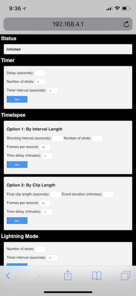
- Creates a WiFi network called Camera__Control and serves up a basic web page that can be accessed by any client connected to it. The network SSID name and WPA Password are hard coded on the Arduino Sketch, but can be easily changed.
- Shows the following information on the OLED screen: Controller IP address, battery charge, number of clients connected and current status.
- Once a client is connected to the controller and accesses the web page, fills out the required fields for a particular task and taps on Start , the Arduino program executes said task (i.e. Timer, Timelapse or Lightning Mode) and updates the Status section at the top of the webpage.
Final Assembly #
Given the modular nature of Adafruit’s Feathers and FeatherWings, putting together the device is pretty straightforward. Just solder the headers to the PCB’s and assemble them.
The most challenging part might be transferring the connections made on the breadboard to the Perma Proto Bonnet. Carefully follow the connections on the diagram shown above (General Setup section) and keep in mind the Perma Proto Bonnet extends the GND and +V pin connections to the opposite side of the board. This greatly facilitates the soldering operation. See images below of the finished board as reference.
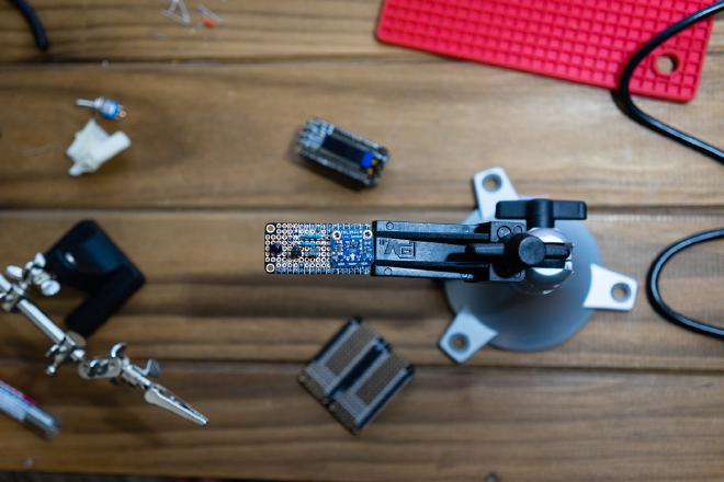
Make sure to solder the VCNL4010 board first as shown, so that there is enough space left for the other components and both set of headers (top and bottom).
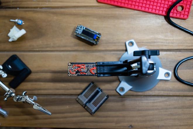
Once all boards are stacked on the Adafruit Doubler and the first section of the switch wire is soldered to the PCB, the whole arrangement can be placed inside the 3D printed case. Then, the on/off switch can be inserted in the case opening and the switch wires can be soldered together and shrink-wrapped as seen below.
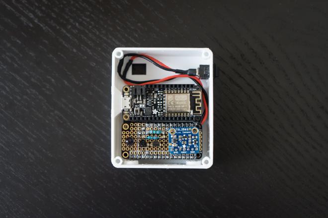
Now, the OLED FeatherWing can be placed on top of the Feather Huzzah and the 3D printed enclosure can be put together.
3D Printed Case #
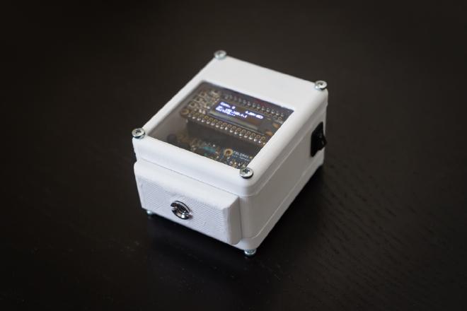
I designed a 3D printed case which can be downloaded fromthe repository (STL files). It has a compartment for the battery so it can be easily detached or swapped with one with smaller/larger capacity. The case also has a USB port opening for charging and programming the device.
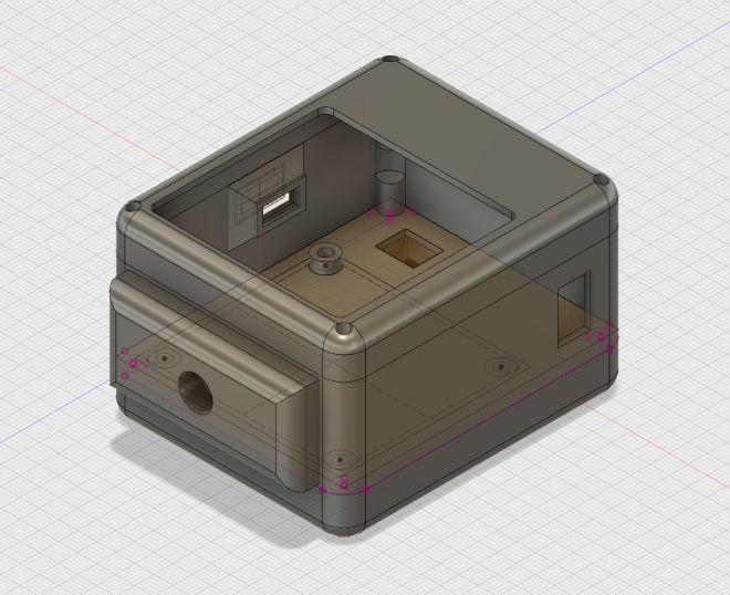
When taking time-lapse photos, the camera will most certainly be on a tripod or attached to a suction cup rig looking out of a high rise building window (this one works great). Under those circumstances, it may be difficult to place the controller near the camera so the IR blast is picked up. For that reason, I have provided the case with four strong magnets at the base, so it can be easily attached to metallic objects. I’ve also designed a little tripod mount which also attaches magnetically to the case.
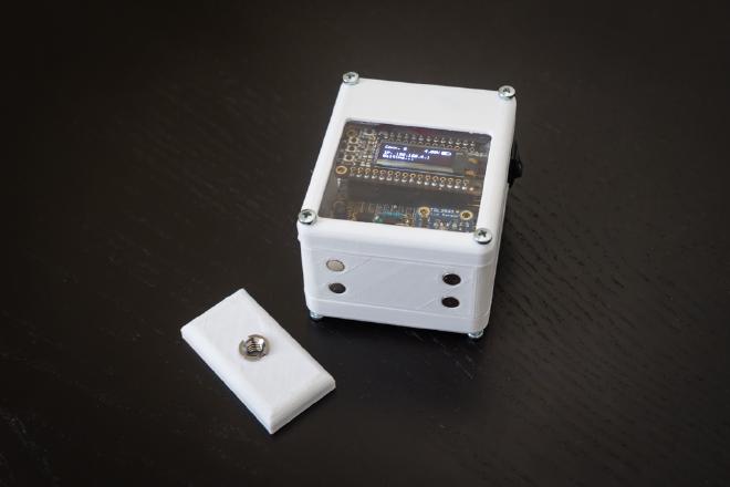
Please, be aware that although the magnetic attachment is fairly strong and can hold the controller at any angle, it is not shock proof. So be mindful of this when using it outdoors.
Finally, although it can’t really be noticed in the pictures, I glued a small acrylic sheet cut to size underneath the main lid, covering the large opening, to keep dust and/or debris from getting inside the case.
Feel free to leave a comment below if you have questions or need any help putting this little controller together.